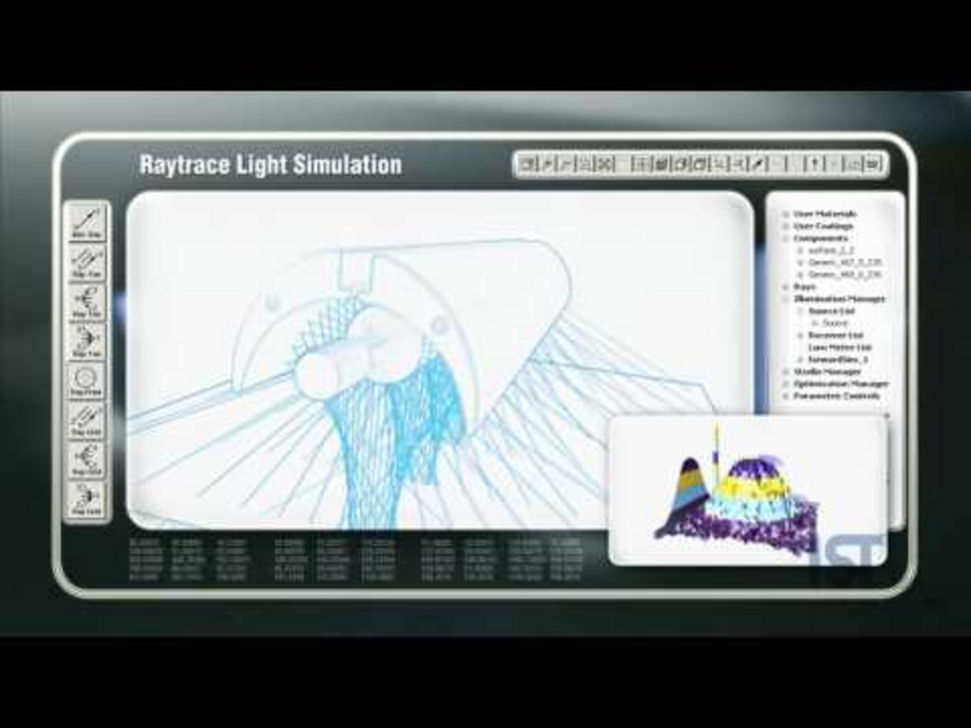
We carry out precise optical simulations to maximise the efficiency of our UV, LED UV and excimer systems. We optimise the geometry of the reflectors using state-of-the-art UV equipment. The UV lamp and reflector are imported into the simulation software as 3D models. Static receiver planes, which are representative surfaces for UV drying, are simulated at different distances. The lamp axis and typical distances to the printing or coating material are decisive here.
Different reflector geometries specifically influence the beam path: Elliptical reflectors focus the radiation, while parabolic reflectors generate a wide spread of radiation. The radiant power is measured per area and visualised in 3D diagrams as watts per square millimetre.
The homogeneity of the radiation and the spacing characteristics are precisely calculated using ray tracing and optimised for highly efficient UV aggregates. These simulations can also be used to determine the number of systems and their positions in order to ensure the required dose on the product to be dried. For UV drying applications on 3D parts in particular, these simulations help to determine the ideal position of the system and avoid shadow areas.
The thermodynamics are optimised in a further development step. The unit is now read into the program as a 3D model, in order to simulate the speed profile of the flow of air and the thermal load of the air, reflectors and housing components alongside the UV unit. Critical zones can be recognised and their dynamics can be optimised. Ray tracing and thermosimulation considerably shorten development times, as the design of both reflectors and housing components can be modified immediately in the 3D CAD system following an optimisation process. Thanks to these simulation programs, time-consuming test set-ups in the laboratory are reduced to a minimum.